Relay Contact Ratings: NEMA ICS5-2017

The “NEMA Standard ICS 5-2017” standard applies to general-purpose mechanical, electro-mechanical, and solid-state devices that are principally used in industrial applications for control-circuit switching and the control of solenoids rated not more than 600 volts.
Understanding Relay Contact Ratings
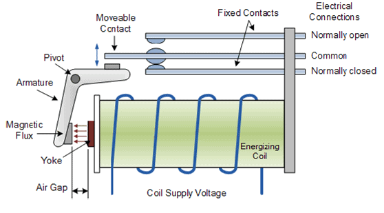
For purely resistive loads, calculating the required contact ampacity is a relatively simple application of Ohms Law. However, when the control circuit involves a solenoid (such as the coil and armature of a contactor), considerations of inrush current and inductive effects come into play.
Make Ratings
- When a solenoid is first energized, it draws an inrush current that can be several times the steady-state current draw.
- To account for this short duration surge in current the standard defines “make” values for when the contact closes and energizes a solenoid coil.
- Make ratings may be larger than the continuous thermal rating because of the very short duration of a coil’s inrush current (typically 30ms or less).

Break Ratings
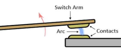
When a contact opens or “breaks” the circuit, it must be able to withstand the arcing that occurs as the contact faces separate. In DC circuits, arcing is exacerbated by the inductive effects of any contactor and relay coils in the circuit that are being de-energized when the contact opens.
Continuous Thermal Current
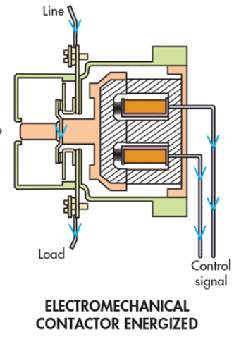
Mechanical contacts inherently introduce a small amount of resistance to the electrical circuits they are part of. Ohms Law tells us that this resistance generates heating effects that are proportional to the current flowing through the circuit. The tests prescribed in ICS 5-2017 stipulate the maximum allowable temperature rise for a given current flowing through the contacts.
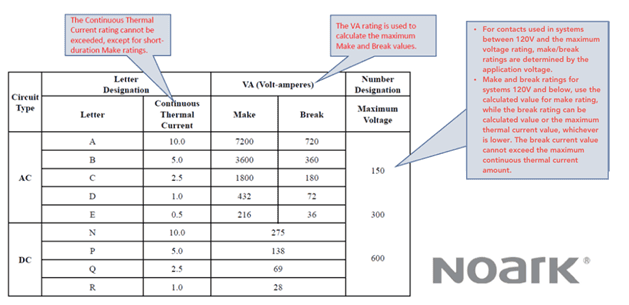
Understanding Contact Rating Designations
Mechanical relay contact ratings are designated separately for AC circuits and DC circuits using a NUMBER/LETTER combination:
- The letter designates maximum continuous current.
- The number designates the maximum voltage rating.
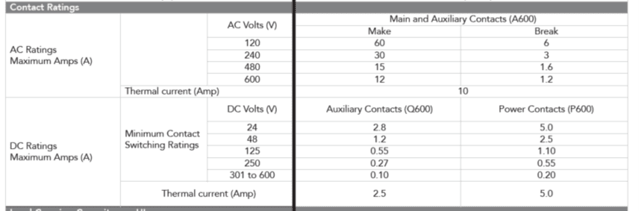
This chart illustrates the key ratings of relay contacts under the standard. Since the voltage and current ratings are MAXIMUM values, the table lists VA (Volt-Ampere) values that are used to calculate the specific permissible current at any given voltage used in the relay’s application.
Applying the Relay Contact Ratings
Example 1:
A contact tested to A300 is used in a 277Vac application:
- Letter Code A = 7200VA (make) & 720VA (break)
- Maximum Continuous = 10A
- Make = VA {make} / Voltage = 7200 / 277 = 25.9A
- Break = VA {break} / Voltage = 720 / 277 = 2.59A
Example 2:
A contact tested to B150 is used in a 24Vac application.
- Letter Code B = 3600VA (make) and 30VA (break)
- Make = 3600 / 24 = 150A
- Break = 360 / 24 = 15A
- since the break rating cannot exceed the thermal rating, the maximum break rating is 5A
Example 3:
A contact tested to Q150 is used in a 125Vdc application.
- Letter Code Q = 69VA (make & break)
- Make and Break = 69 / 125 = 0.52A
Example 4:
A contact tested to N150 is used in a 24Vdc application.
- Letter Code N = 275VA (make & break)
- VA Calculation for make & break: 275 / 24 = 11.45A
- Make = 11.45A
- Break = 11.45A
- since the break rating cannot exceed the maximum thermal value, the maximum break rating is 10A.
Stay Up to Date with NOARK Electric
To stay up to date with industry news, product releases, and free downloadable resources, subscribe to the NOARK Newsletter today.


Understanding Ground Fault Protection: Importance and Implementation
In this blog, we will delve into the significance of ground fault protection and explore the various methods of implementation.
Read More
The Purpose of Arc Flash Reduction Maintenance Switch Systems
Recognizing the need for enhanced safety measures, engineers have developed the Arc Flash Reduction System to address the risks associated with arc flashes. Arc flash reduction systems are an advanced technology integrated into modern circuit breakers to minimize the occurrence and severity of arc flash events. It operates by detecting the onset of an arc […]
Read More
Arc Flash Reduction: Defending Against Electrical Hazards
Ever wondered what Arc Flash Reduction is? This Tech Tip helps readers understand what it is and why it’s important to mitigate the impact.
Read More